![]()
Moore Family
of Arizona


|
Moore Family
|
|
|
Audio Power Supply Changes: In redesigning my car Audio system I decided on a complete change to the way power is supplied. part of my motivation was the much more complicated configuration as well as a desire to reduce system noise which my old system was somewhat susceptible to. The Audio equipment changes I made were:
In order to support these effectively I also added the following as clean power solutions:
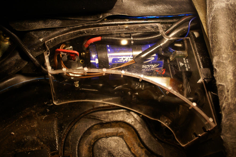
This was a major rewire but only a small amount of added work to the total Audio system package. My Audio supplies are now switched on with the accessory switch, disabled during starting and stay on until a door is opened - even after the ignition is turned off. If the head unit is activated while the key is out the audio system turns on with a 1 hour timeout controlled by the head unit. The Phone system, Valentine radar detector and iPod interface are also all powered by the audio supply system. Below is the location of the decoupling capacitor - right above and in front of the battery box - in the spare tire well. There is a plastic cover over this area which I replaced with a lexan cover I made since the capacitor needed additional space - it barely fits. Cars with PSD (like mine) have a little less room in this space (due to PSD relay & fuse). To the left of the capacitor is the capacitor switch with integrated charging resistor & LED. In the final version I cut the switch handle off and cut a screwdriver slot into the end and drilled a hole in the top cover directly above it. This allows operation of the switch with a screwdriver by just lifting the edge of the hatch area carpet cover. The capacitor switch switches the ground of the capacitor.
|
|
Copyright (c): Alan Moore 2006 - 2014
Page Updated:
12/16/2014
Page Views:
|